
Introduction
The process of tool design and prototyping relies on 3D modeling to support both innovative developments and precise engineering work. The husky ratcheting screwdriver end cap 3D model design process uses a small component which impacts the design of the screwdriver through its effects on user comfort and operational capabilities and product longevity. The end caps establish structural support which helps users operate the ratcheting system and improves their overall experience. Designers can use 3D models to create custom prototypes which enable them to verify product design and functionality. The industrial sector and hobbyist activities and CAD simulations all depend on 3D models which need to be created with precise design methods to guarantee optimal product performance and compliance with quality requirements. The guide provides a complete process for building a husky ratcheting screwdriver end cap 3D model which includes all essential design elements and practical advice for CAD modeling and 3D printing.
Step 1: Understanding the Component
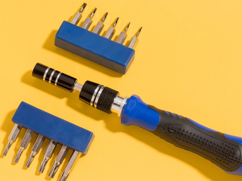
Before diving into CAD software, it is important to understand the husky ratcheting screwdriver end cap and its purpose. The end cap serves multiple functions:
- Protects the internal ratcheting mechanism from dust and debris
- Provides a secure closure to the handle
- Offers ergonomic support for comfortable use
- Often includes a magnetic insert or hole for retaining small bits
Designers need to examine the existing screwdriver or technical specifications to capture dimensions, tolerances, and functional requirements. Measuring the diameter, depth, and threading details ensures the 3D model will be accurate and fit perfectly when assembled.
Step 2: Choosing the Right 3D Modeling Software
The next step is selecting software suitable for creating precise 3D models. Popular CAD tools for mechanical components like end caps include:
- SolidWorks: Ideal for parametric designs and assemblies
- Autodesk Fusion 360: Great for beginners and rapid prototyping
- TinkerCAD: Useful for simple geometric designs and hobbyist projects
- PTC Creo: Used in industrial and professional tool design
The choice of software depends on your expertise, project complexity, and output needs. For professional-grade designs, SolidWorks or Fusion 360 is recommended due to robust parametric modeling capabilities.
Step 3: Creating the Basic Shape
Start by creating the basic cylindrical shape of the end cap. In most screwdrivers, the end cap is round, with slight tapering to ensure a snug fit. The steps include:
- Sketch the Cylinder: Define the outer diameter and height according to measurements.
- Extrude: Convert the 2D sketch into a 3D cylinder using the extrude tool.
- Hollow Interior: Use the shell function to hollow out the interior if necessary, accounting for the ratcheting mechanism.
At this stage, keep in mind functional elements like insertion points for ratchet pins or slots for alignment. Maintaining precise tolerances is crucial to ensure the model fits correctly.
Step 4: Adding Functional Details
Functional details make the model realistic and usable. These may include:
- Threading or Snap-Fit Features: Some end caps screw into the handle or snap securely. Using the thread tool in your CAD software can simulate threading.
- Holes or Inserts: If the screwdriver has a magnetic bit holder, include a central cavity or hole.
- Ergonomic Shapes: Add slight contours or fillets to improve user comfort during use.
These details not only improve aesthetics but also ensure compatibility with the screwdriver’s internal mechanism.
Step 5: Refining the Model for Accuracy
The 3D model needs to undergo precision updates after functional details have been added. The dimensions should match the actual component measurements without any errors. The evaluation needs to include tolerances together with wall thickness and fillet radii specifications. CAD software simulation tools enable users to assess both the structural strength and ergonomic design of their models. The material properties must be evaluated during this phase when creating 3D printing or prototyping models. End caps require materials with exceptional durability which the CAD model must include additional shrinkage and flexibility and strength specifications.
Step 6: Preparing for 3D Printing or Prototyping
Once the CAD model is finalized, prepare it for 3D printing. Export the model in compatible formats such as STL or OBJ, commonly used for slicing in 3D printing software. Consider the following:
- Layer Height: Adjust for resolution and strength. Smaller layers give smoother surfaces.
- Infill Density: Higher infill strengthens the end cap, essential for functional prototypes.
- Support Structures: Ensure supports are added if the design has overhangs or complex contours.
Testing the first print allows you to check fit, alignment, and functionality before mass production or integration into the screwdriver handle.
Step 7: Testing and Iteration
Even with accurate CAD modeling, real-world testing is crucial. Assemble the printed end cap into the screwdriver and verify:
- Snug fit without excessive friction
- Smooth ratcheting operation
- Proper alignment with internal mechanisms
- Comfort and ergonomic handling
Iterate the model as needed, adjusting dimensions, tolerances, or features to improve functionality. Multiple iterations often lead to a more refined, high-quality end cap suitable for both prototypes and final products.
Benefits of 3D Modeling Husky Ratcheting Screwdriver End Caps
Creating a husky ratcheting screwdriver end cap 3d model offers multiple advantages:
- Enhanced Design Accuracy: Captures precise measurements and tolerances.
- Rapid Prototyping: Quickly test and modify designs without manufacturing delays.
- Cost-Effective: Reduces the need for expensive molds or traditional machining.
- Customization: Enables personalized end caps for different tools or user preferences.
- Simulation and Testing: Allows stress tests and ergonomic assessments digitally before production.
Conclusion
The process of creating a 3D model for a husky ratcheting screwdriver end cap requires designers to complete multiple stages which include accurate measurements, appropriate software choice, system design work, and multiple rounds of testing. The process of creating an end cap model begins with components analysis, which leads to basic shape creation, then functional element addition, followed by dimension adjustment, and finally 3D printing preparation. 3D modeling serves as an economical solution for developing essential tool components which benefits both product development and prototyping work as well as recreational projects. The steps described in this section provide designers and engineers with a method for creating end caps which improve tool performance and user experience and tool lifespan.
FAQs About Husky Ratcheting Screwdriver End Cap 3D Model
1. What is a husky ratcheting screwdriver end cap 3D model?
It is a digital 3D representation of the end cap component of a Husky ratcheting screwdriver, created using CAD software for design, prototyping, or manufacturing purposes.
2. Which software is best for modeling the end cap?
SolidWorks, Autodesk Fusion 360, and PTC Creo are commonly used for precise CAD modeling of mechanical components.
3. Can I 3D print the end cap?
Yes, once the 3D model is finalized, it can be exported as STL or OBJ files and 3D printed using appropriate plastic or composite materials.
4. What should I consider when designing the end cap?
Key considerations include dimensions, tolerances, threading or snap-fit features, ergonomic design, and material properties.
5. How can 3D modeling improve screwdriver design?
3D modeling allows rapid prototyping, design iteration, testing for fit and ergonomics, and cost-effective customization.